The design of a river crossing considers environmental standards with respect to channel equilibrium and aquatic organism passage, as well as hydraulic design criteria, as detailed in the VTrans Hydraulics Manual. State of Vermont hydraulic and environmental standards are summarized as follows:
Headwater Depth
Headwater depth pertains to the depth of water upstream of the structure inlet. The allowable headwater depth, at the design flow of interest, is compared to the depth of a structure opening (also called the structure rise or clear height). The allowable headwater to depth ratio (HW/D), for the respective structure size, is tabulated in Hydraulics Manual Table 6-3, and summarized as follows:
- Culvert Rise ≤ 36 inches: HW/D ≤ 1.5
- Culvert Rise > 36 inches: HW/D ≤ 1.2
- Culvert Rise > 60 inches: HW/D ≤ 1.2, in addition HW/D ≤ 1.5 at the 1% AEP storm event
More Information: Hydraulics Manual, Section 6.4.2.1: Allowable Headwater and Backwater
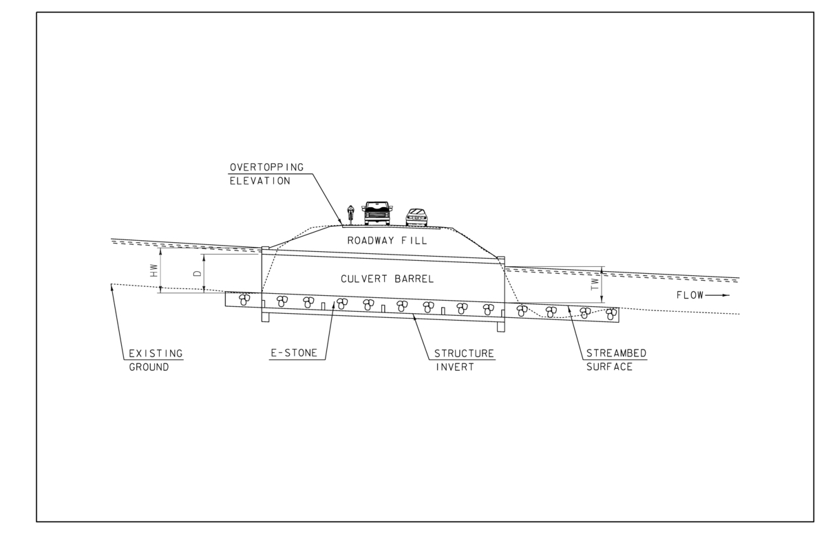
Figure 3: Culvert profile in high water. In this figure, headwater depth (HW) exceeds that of the waterway opening depth (D). The ratio of headwater depth to opening depth (HW/D) at the design frequency is one of the key factors in determining the hydraulic adequacy of a structure. This figure also displays the tailwater depth (TW), the depth of water downstream of the structure outlet; and the structure invert- the bottom chord of a closed bottom culvert. When computing HW/D ratios for an embedded culvert, it is important that headwater and structure depth be measured from the streambed surface. This means that a culvert with a total rise of 6 feet, with the structure invert embedded 2 feet below the streambed (infilled with 2 vertical feet of E-stone), provides a 4-foot waterway opening depth (D). This opening depth (clear height), is thus relative to the same datum as the headwater, providing a fair comparison for determining hydraulic adequacy.
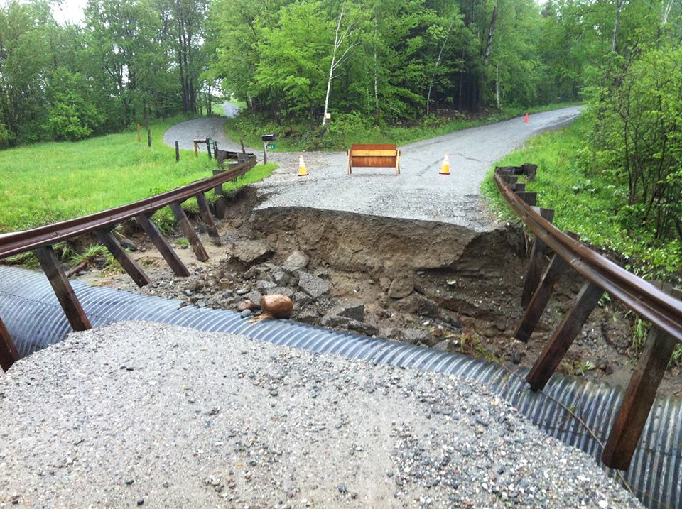
Figure 4: A large headwater to depth ratio indicates that the structure does not have sufficient hydraulic capacity. When a structure is hydraulically undersized, the hydraulic model indicates that headwater depths rise past the allowable threshold in the design event, putting the roadway at risk of washing out and increasing water surface elevations upstream.
Freeboard
Freeboard is the vertical distance between the water surface elevation (WSE) and the lowest point on the bottom of a bridge (low chord). To meet the VTrans hydraulic standard, there must be no less than 1 foot of freeboard at the design flow. This standard is applicable for all open bottom structures, regardless of structure type.
More Information: Hydraulics Manual, Section 6.5.1.2: Freeboard

Figure 5: Warren Covered Bridge, constructed in 1880 (left) and the Waitsfield Covered Bridge (Great Eddy Bridge), constructed in 1833 (right). Freeboard is shown for the Warren bridge in a low flow condition. By contrast, the Waitsfield structure is experiencing flooding from the July 1st, 2017 event. Minimal freeboard is known to cause issues with debris passage. If not rectified, debris can continue to build up, reducing the capacity of the crossing and raising floodwater elevations upstream. This structure was shut down for just one night while local responders worked to cut the tree in half. The bridge was declared safe for traffic the following morning.
Overtopping
The vertical height from the streambed to the roadway may be a limiting factor, even when headwater to depth criteria is satisfied. Overtopping occurs when the headwater elevation exceeds the roadway elevation. Overtopping is not permissible at the design flow.
More Information: Hydraulics Manual, Section 1.3.4.2: Hydraulic Adequacy
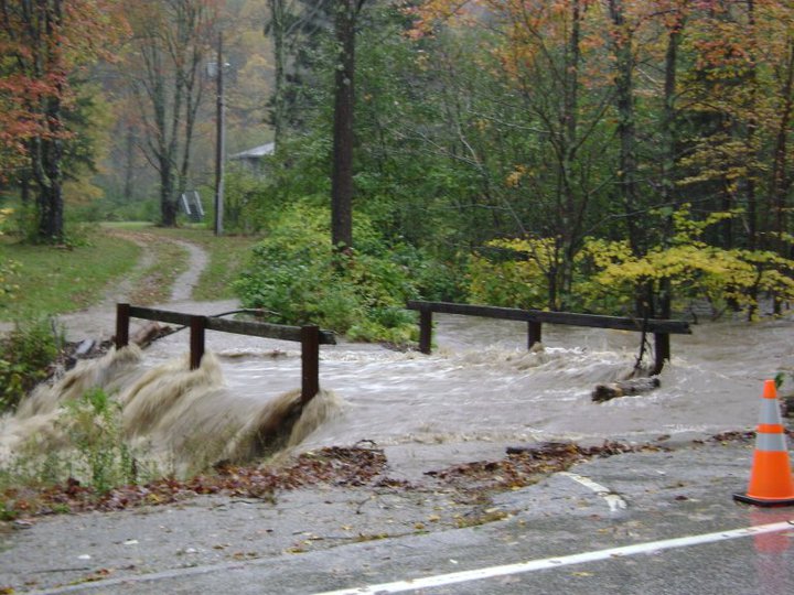
Figure 6: Water overtopping the roadway is not permissible at the design flow, but may occur at flows exceeding this threshold. VTrans calculates a check flow for each structure, generally the 1% AEP event (freeways crossings the 0.2% event as the check flow). Although the structure is not designed for this magnitude event, further mitigation can be taken to minimize impacts on the structure and surrounding landscape (E.g. stone to dissipate energy and protect against erosion, installation of a relief structure to reduce headwater depths, etc.).
Stone Fill
E-stone, or environmental stone, is primarily used within perennial streams. E-stone has fine sized material that fill in voids, ensuring that flow is kept above the surface. VTrans stone fill has minimal fines, if used within the channel it has been known to cause subsurface flow which is not conducive to Aquatic Organism Passage (AOP). VTrans stone fill is generally used to protect channel banks and/or abutments from erosion and scour. Stone fill should be larger than or equal to the size of unmoved natural stone. Current stone fill design practice emphasizes outlet velocity as a means of determining adequate stone fill sizing. The following resources are consulted when sizing stone fill based on velocity.
More Information: Hydraulics Manual
- Section 5.3.2: Stream Channels
- Section 6.4.4.2: Outlet Protection
- Section 6.4.3.4: Embedded Materials

Figure 7: Stone fill applied to protect the roadway slopes and channel banks from erosion (left). Hydraulics Manual Table 5-1 provides guidance for sizing VTrans stone fill based on design flow velocity. This type of fill should be used to protect disturbed channel banks or roadway slopes at the structure’s inlet and outlet, up to a height of at least one-foot above the top of the opening. It should not constrict the channel or the structure opening. Type I stone is generally used for roadway ditches rather than stream crossings. Guidance for roadway ditch design may be found in the Hydraulics Manual, Table 5-3.
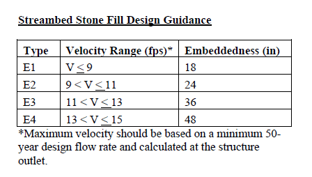 Figure 8: Table for E-stone design size and the associated infill and structure embedment depths. E-stone includes fine material to fill voids between the larger stone, preventing subsurface flow which would otherwise inhibit aquatic organism passage. E-stone is sized in accordance with the 2% AEP outlet velocity. Each stone size corresponds to a particular embedment depth. Closed-bottom structures on perennial streams should be embedded below the streambed at the corresponding depth, and filled level to the streambed with the specified E-stone.
Channel Equilibrium
State stream equilibrium standards require structures to span the natural channel bankfull width (BFW). Bankfull width, in essence, is the most active portion of the channel. Structures sized in accordance to the local bankfull width maintain natural channel velocities and increase the likelihood that the structure will pass natural debris. If a structure constricts the channel width, it is known to cause ponding at the inlet, increase stream velocity and scour at the outlet, and may also lead to erosion and failure of channel banks. By contrast, a structure that spans larger than BFW is more prone to fill in with streambed material (aggregation), restricting the waterway area and hydraulic capacity of the structure. For information on identifying bankfull width see Vermont Stream Geomorphic Assessment: Identification of Bankfull Stage.
More Information: Hydraulics Manual
- Section 3.2.3.3: Stream Cross Sections;
- Section 5.2.4: VT Department of Environmental Conservation Guidelines
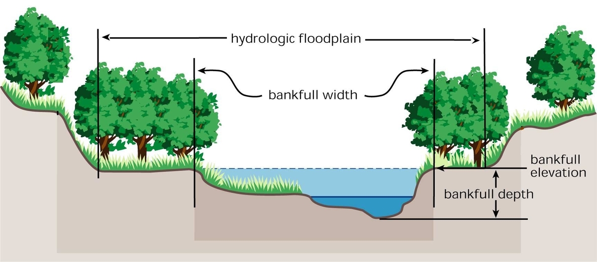
Figure 9: Identification of bankfull width. When sizing BFW, both upstream and downstream are surveyed to determine the natural channel width that should be maintained through a crossing structure. Historically, many structures in Vermont are undersized, which has led to issues with erosion and channel equilibrium. For more information on bankfull width and how this contributes to the five stages of channel evolution, see the Vermont Rivers and Roads Field Manual.
Aquatic Organism Passage
Stream crossing structures within perennial streams (a stream that continuously conveys surface water) are important transportation networks, connecting fish and other organisms to spawning habitat and promoting genetic diversity. Aquatic organism passage (AOP) encompasses several features in bridge design that serve to ensure the passage of aquatic organisms within perennial streams. Barriers to AOP are commonly related to velocity, depth and turbulence. Maintaining natural channel geometry through the structure is essential for providing the continuity and consistency needed for AOP. This is achieved by sizing the structure span in accordance to the local stream bankfull width and replacing distrubed channel sections with E-stone (see Stone Fill), allowing flow to be kept above the surface.
More Information: Hydraulics Manual
- Section 6.4.2.7: Aquatic Organism Passage
- Section 5.2.4: VT Department of Environmental Conservation Guidelines
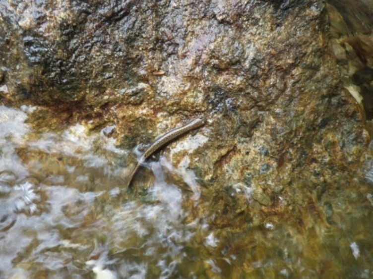
Figure 10: Aquatic organism passage is commonly associated with trout spawning habitat, but also encompasses connectivity for many other species, such as this Northern Two-Lined Salamander, pictured above in the Mill River of Mount Holly, VT. This species, along with the Northern Dusky and Spring Salamanders, are a few of the many commuters that regularly traverse perennial streams in Vermont. The Northern Two-Lined and Spring Salamanders wander away from streams into adjacent woodlands to feed on rainy nights. To minimize ecological impact, it is imperative that aquatic organism passage be facilitated for crossing structures within perennial streams.
Previous page: Hydraulic Studies
Next Page: Hydraulics Typical Drawings
